Charlieplexing
Charlieplexing is a technique to control many more devices (usually LEDs) than you would be able to do with a conventional matrix. It's actually quite similar to a matrix, and just as fast and flexible, if you know how to wire things up. In this post I'll be focusing on LEDs but note that this can also be used for buttons.
The main trick that charlieplexing uses is that pins can be set to three states (not just two): high, low, and floating. Floating meaning it isn't explicitly high or low (source or sink), usually by setting the pin as "input" or "analog".
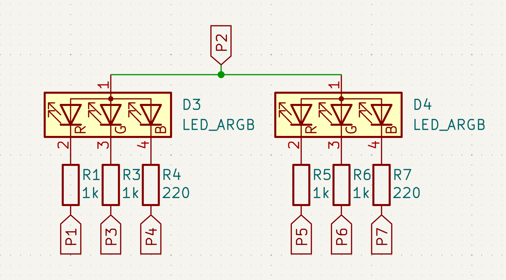
Let's get started with just a single row of LEDs:

That's two RGB LEDs, so six LEDs in total. (Yes, we're going to use RGB LEDs for our charlieplexing examples)! Of course these are LEDs, so you will need to have some resistors in place too. And resistor values may vary between LED colors, in this case we're going to use 1kΩ resistors for the red and green LEDs and 220Ω for the blue LEDs.
The way to control this row of LEDs is as follows. Initially all pins are floating, and then:
- Set
P1high. - Toggle all other pins (
P2-P7) to low and back to floating, for a specific duration (depending on the intended brightness). To make the output look good, you can do this for all 6 LEDs at once - as long as they all return to floating in the end. - Set
P1back to floating.
Ok, that's nice. A single row of LEDs, controlled in a somewhat complicated fashion.
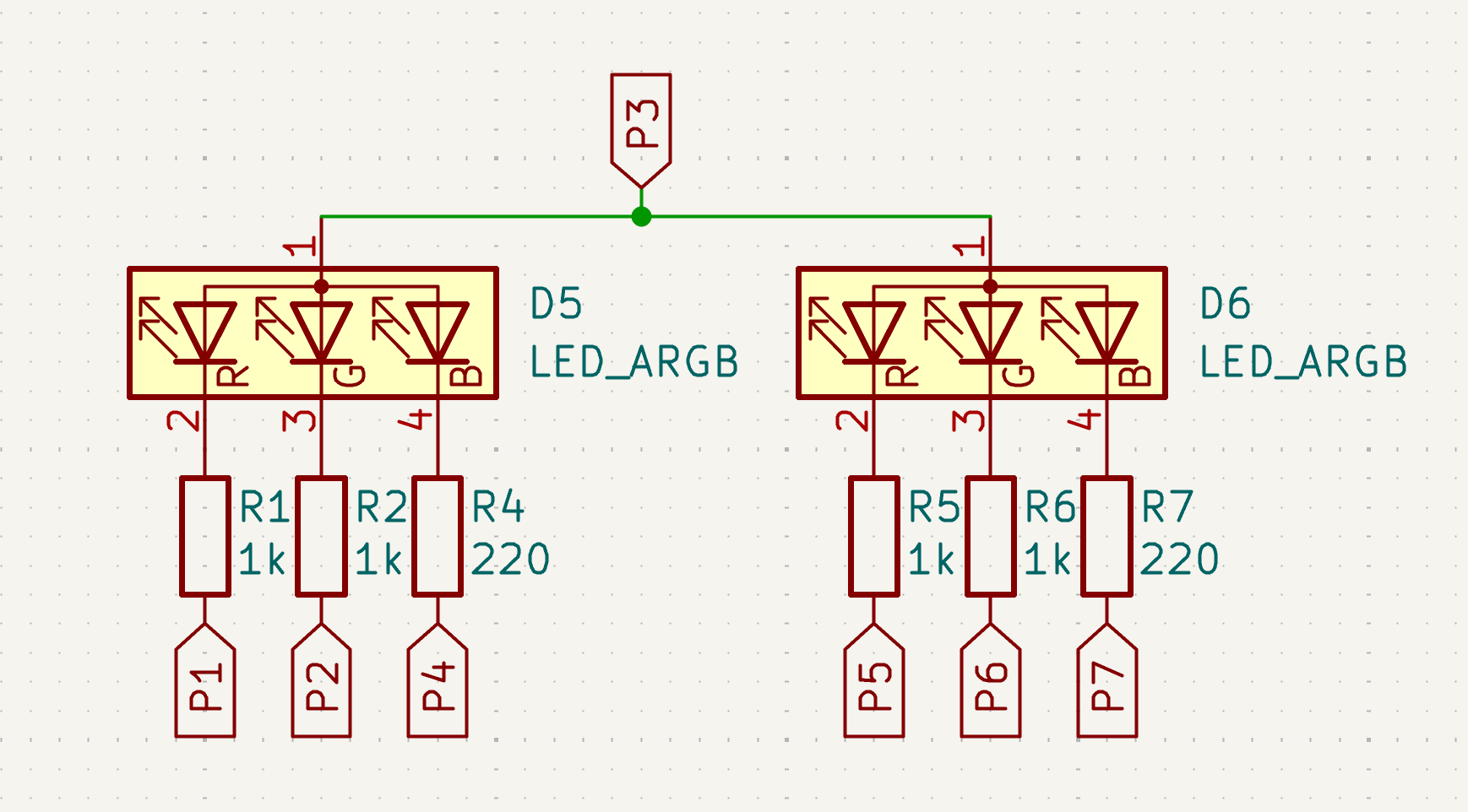
Let's see the next row of LEDs:
This is almost the same - but note that P1 and P2 have been swapped. There are still 7 pins, but the anode (on the top) is now P2 instead of P1. Otherwise the schematic is basically identical.
Let's try those steps again, but now with P2:
- Set
P2high. - Toggle all other pins to low and back to floating.
- Set
P2back to floating.
This works just as well as before. But we're reusing pins from before! Do they conflict? In fact, they do not, since we're using LEDs which are diodes - they only carry current (and therefore light up) in a single direction:
- Setting P2 to high won't affect the one LED it is connected to in the first row, since it just puts power on the cathode of the LED. The diode will block current flowing in that direction.
- Setting P1 to low won't affect any of the LEDs in the first row, again because they're all diodes.
- Since none of the LEDs in the first row get a voltage on the anode, setting any of the cathodes on the bottom of the first row (
P3etc) to low won't affect them.
And since we literally just swapped P1 and P2, it should be trivial to see that the inverse is also true: controlling the first row won't affect the second row.
Okay, let's look at a third row of LEDs:
We're just using the next available pin here, P3. And just as before, setting this pin to high allows us to control this row of LEDs by toggling the cathode pins at the bottom between low and floating.
We could continue here for four more pins (P4 to P7), but the basic pattern is the same. All combined we will have a matrix with 7 rows and 6 colums (if we count the individual LEDs).
The intuition I use is that of power flowing in a particular direction across a row of LEDs. To control a row of LEDs, you set the shared anode pin (and only this pin) to high, which allows current to flow from that direction. And the other cathode pins will either receive current (when low) or will be floating and therefore disconnected.
With this intuition, it's trivial to see how many LEDs you can control with a given number of pins: N * (N-1) with N anodes (rows) and N-1 cathodes (columns). You can also do the reverse calculation, but in practice I find it easier and more intuitive to calculate the number of LEDs from the number of available pins.
Note however that if you are using RGB LEDs, as in the examples above, you can't always control as many LEDs as you would calculate with the above formula since the number of colums isn't always a multiple of 3. To calculate the number of possible RGB LEDs, you can use a formula like N * floor((N-1)/3).
Controlling a matrix
The way these LEDs are controlled in practice is by rapidly going over each row in turn, bitbanging them. This means these LEDs are only on for a short duration, depending on the number of pins you have available. But this is not necessarily a problem! The LEDs might be on for only 5-10% of the time but that's often plenty bright for modern high-efficiency LEDs (high mcd per mA).
The same problem exists for conventional LED matrices. In that case, you can only light up a single row at a time - just as with Charlieplexing. So Charlieplexing doesn't really have a disadvantage here.
Also, I recommend you read my next post on bitplanes for a technique to turn a row of LEDs on for a specific duration that differs per LED. It's quite a nifty technique!
Optimizing resistors
You might have noticed that every LED in the above examples has its own resistor. But this is not necessary in practice - you can share resistors between LEDs. For example, R3-R7 in the first two rows can be the same as R3-R7 in the second colunn. And for the third row, all resistors except for R2 can be shared with the second row. So in the ideal case (with all the same resistor values) you can in fact just use 7 resistors. With varying values, you may need to have different groups of resistors: 2 or 3 resistors per GPIO pin for the different resistor values connected to the variously colored LEDs.
Limitations
I hope that with this post I've shown that Charlieplexing can be just as powerful as a LED matrix while using far fewer pins. And also that it can be used to control RGB LEDs. However, Charlieplexing is not without problems:
- It doesn't work if the GPIO voltage is too high. If you have an older microcontroller running at 5V, some power may flow across two red LEDs while controlling a blue LED. In my experience, it works fine at 3.0V and 3.3V.
- Some microcontroller have limitations on how fast you can switch between input and output. I've had some weird ghosting on an STM32L0 chip at least that I couldn't really explain (running at a lower frequency made the ghosting disappear).
- Controlling a whole row of LEDs with just a single GPIO pin may be too much for that pin. Looking at datasheets, it appears that GPIO pins have an internal resistance of around 20-100Ω (this isn't spelled out in the datasheet directly but you can calculate it based on the GPIO voltage vs source/sink current). Also, many GPIO pins aren't rated for very high current: depending on the microcontroller this may be about 8mA to 20mA. But if you make the LED resistor values large enough, this might not be a problem in practice.
Conclusion
I hope I've convinced you that Charlieplexing is actually pretty neat! It uses about half the number of pins as a matrix and works just as well if you apply some optimizations.
One place I've used Charlieplexing is in my 36-LED earrings. With a conventional matrix I would have needed 21 pins and a lot more complicated routing, and the chip I use on the earrings doesn't even have that many GPIO pins. Here I've used 12 pins to control all 36*3=108 LEDs.
Next up: how to bitbang matrices using binary coded modulation.